Our Goal
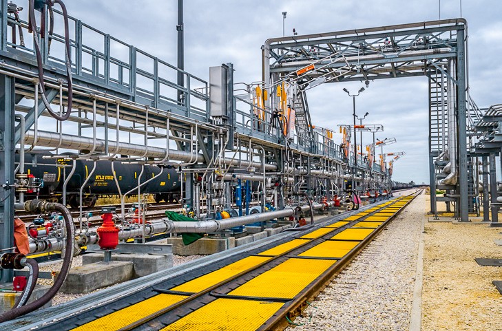
LJA’s mission for this project was to design a Turn-Key Crude Oil Terminal for GT Logistics located on 1,200 acres in Port Arthur, Texas. This project consisted of four 45,000 BBL crude storage tanks with floating roofs, as well as approximately nine miles of new track alignment, including a loop track of sufficient length to accommodate unit train handling, six 3,500-foot storage tracks, and two 3,500-foot tracks to be used for the unloading of crude oil from unit trains. The crude-by-rail operation is capable of transferring 100,000 barrels of oil per day.
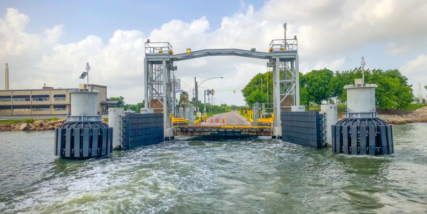
In addition, the project included a new rail bridge, an 18-slot rail car unloading rack, and a new barge dock for loading two 30,000 BBL crude barges simultaneously, and marine vapor control system. Unit trains of up to 130 cars can be received at a time with operating systems in place to unload and release these trains within 24 hours of arrival.
The LJA Roadmap
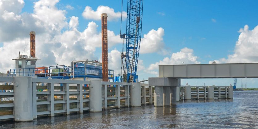
LJA’S roadmap included determining horizontal and vertical alignments, as well as coordinating pipeline and other utility crossings. Our team also provided the engineering and design of two steel bridges for crossings of the Lower Neches Valley Authority canal that transects the site.
Key design contributions:
– Drainage from the 1,200- acre site, including five box culvert crossings of the rail alignments that were considered bridge-class structures by Union Pacific.
– Rail car unloading system, dual 16-inch, one mile in-boundary limits pipelines, and a barge dock to load crude.
– Pipe bridge spanning 200 feet across a hurricane protection levee requiring a United Sates Army Corps of Engineers (USACE) 408 permit.
What We Offered
- Permitting
- Process
- Piping Design
- Fire Suppression
- Civil Engineering
- Coastal Engineering
- Project Engineering
- Electrical Engineering
- Structural Engineering
- Mechanical Engineering
Ensuring Safety
Bridge class structures were designed to conform to American Railway Engineering and Maintenance-of-Way Association (AREMA) standards. Fire suppression foam systems were sized for foam application rates and durations in accordance with NFPA 11 and included wet wells, pumps, piping, monitors, and foam dosing equipment.


